Engineering graphics provides standardized methods for creating precise technical drawings, enabling effective communication of design ideas and specifications across various engineering disciplines and industries.
1.1. Definition and Purpose of Engineering Graphics
Engineering graphics is a systematic approach to creating technical drawings using standardized rules and conventions. Its primary purpose is to communicate design ideas, schematics, and models with precision and clarity. By following established guidelines, engineering graphics ensures that drawings are universally understood, facilitating collaboration across disciplines. This method is essential for transforming abstract concepts into tangible visual representations, which are critical for manufacturing, construction, and engineering applications. The detailed nature of these drawings enables professionals to interpret dimensions, materials, and assembly requirements accurately. Essentially, engineering graphics serves as a universal language for engineers, bridging the gap between design and execution, as highlighted in resources like the Technical Drawing with Engineering Graphics PDF.
1.2. Importance of Engineering Graphics in Technical Drawing
Engineering graphics plays a pivotal role in technical drawing by providing a standardized method of communication. It ensures that designs, dimensions, and specifications are conveyed clearly and accurately. This precision is critical for manufacturing, construction, and assembly processes, where misunderstandings can lead to costly errors. Engineering graphics also enhances collaboration among engineers, designers, and technicians by serving as a universal language. Its structured approach reduces ambiguity, making it easier to interpret complex designs. Additionally, it facilitates the creation of detailed documentation, which is essential for project planning and execution. As highlighted in the Technical Drawing with Engineering Graphics PDF, these qualities make engineering graphics indispensable in modern engineering practices.
Fundamental Concepts of Technical Drawing
Technical drawing relies on basic elements like lines, shapes, and symbols to represent objects accurately. These foundational principles ensure clarity and consistency in engineering communication.
2.1. Basic Elements of Engineering Drawings
Engineering drawings are built from fundamental elements such as lines, circles, arcs, and polygons. These elements are combined to represent shapes and forms accurately. Dimensions, including linear, angular, and radial measurements, provide precise specifications. Symbols and notations are used to convey material properties, surface finishes, and manufacturing processes. Tolerances indicate permissible deviations, ensuring fit and function. Titles, notes, and scale bars add context, while grids and reference planes help in aligning and positioning elements. These components ensure clarity, accuracy, and uniformity in technical communication, making engineering drawings a universal language for designers, manufacturers, and engineers worldwide.
2.2. Types of Engineering Drawings: Schematics, Models, and Documentation
Engineering drawings are categorized into schematics, models, and documentation, each serving distinct purposes. Schematics are simplified diagrams that illustrate functional relationships, such as electrical circuits or fluid flows. Models, both 2D and 3D, provide detailed visual representations of objects or systems. Documentation drawings are comprehensive, including all necessary details for manufacturing, such as dimensions, tolerances, and material specifications. These types ensure clear communication of design intent, enabling accurate production and assembly. They are essential for collaboration among engineers, designers, and manufacturers, forming the backbone of technical documentation in various industries.
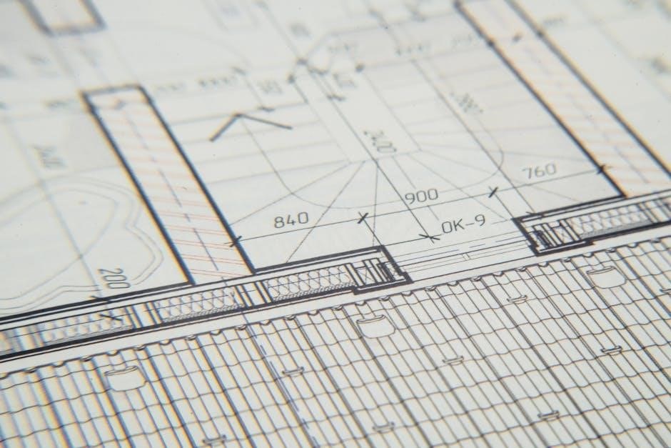
3D Modeling and Documentation in Technical Drawing
3D modeling involves creating detailed digital representations of objects for design and analysis. Documentation includes converting these models into 2D drawings with dimensions and manufacturing details.
3.1. Creating 3D Models for Engineering Applications
Creating 3D models is essential for engineering applications, enabling precise visualization and communication of design intent. CAD software allows engineers to develop detailed digital representations of objects, incorporating geometrical accuracy and material specifications. These models facilitate prototyping, simulations, and manufacturing planning. By integrating technical drawings, 3D models ensure consistency and clarity, aiding in the identification of design flaws early in the process. This approach streamlines collaboration among stakeholders, enhancing productivity and reducing errors. The ability to generate 2D documentation from 3D models further supports manufacturing and assembly processes, making 3D modeling a cornerstone of modern engineering practices.
3.2. Converting 3D Models to 2D Documentation Drawings
Converting 3D models into 2D documentation drawings is a critical step in engineering graphics, enabling the creation of standardized plans for manufacturing and assembly. This process involves generating orthographic projections, such as front, top, and side views, from the 3D model. These views provide precise measurements, tolerances, and annotations necessary for production. CAD software simplifies this conversion by automating the projection of 3D data into 2D formats. The resulting drawings ensure clarity and consistency, allowing manufacturers to interpret the design accurately. This step is essential for transforming conceptual models into actionable blueprints, facilitating seamless communication between designers and production teams.

Orthographic Projections in Engineering Graphics
Orthographic projections are standardized views (front, top, side) used to represent 3D objects in 2D, ensuring accurate and unambiguous communication of design details.
4.1. Understanding Orthographic Views: Front, Top, and Side
Orthographic views are standardized 2D representations of 3D objects, typically shown as front, top, and side projections. These views provide clear, unambiguous details of an object’s features, eliminating perspective distortion. The front view displays the object as seen from the front, the top view from above, and the side view from the left or right. Each view is aligned to showcase specific dimensions and details, ensuring accurate interpretation. These projections are fundamental in technical drawing, enabling engineers and designers to communicate complex shapes effectively. Proper understanding of orthographic views is essential for interpreting and creating precise engineering drawings.
4.2. Applications of Orthographic Projections in Technical Drawings
Orthographic projections are widely used in technical drawings to accurately represent complex objects in multiple views. They are essential for detailing components, assembly drawings, and precision measurements. In mechanical engineering, these projections help visualize machinery and parts from different angles. Architects use them to depict building layouts, while manufacturers rely on them for production planning. Orthographic views ensure consistency and clarity, making them indispensable for international communication in engineering. They are also critical for creating dimensionally accurate documentation, enabling precise fabrication and assembly. By providing unambiguous representations, orthographic projections are fundamental to the design, analysis, and manufacturing processes across various industries.
Computer-Aided Design (CAD) in Engineering Graphics
CAD revolutionizes technical drawing by enabling precise 3D modeling and 2D documentation, streamlining design and documentation processes with advanced tools and databases for efficient engineering workflows.
5.1. Role of CAD Software in Modern Technical Drawing
CAD software plays a pivotal role in modern technical drawing by enabling the creation of precise 2D and 3D models. It streamlines the design process, enhances accuracy, and improves collaboration. With CAD, engineers can generate detailed documentation, simulate designs, and analyze prototypes virtually. Tools like AutoCAD and SolidWorks integrate advanced features such as parametric modeling and rendering, making it easier to visualize complex projects. CAD databases also store design data, ensuring consistency and traceability. This technology has transformed traditional drafting methods, allowing for faster iterations and reducing errors. As a result, CAD is indispensable in industries ranging from architecture to mechanical engineering, driving innovation and efficiency.
5.2. Using CAD Databases for Design and Documentation
CAD databases are essential for managing design data, enabling efficient collaboration and documentation. They store detailed project information, including 3D models, 2D drawings, and specifications. By organizing data centrally, CAD databases ensure version control and traceability, reducing errors. Design teams can access and modify files simultaneously, fostering teamwork. These databases also support the creation of technical documentation, linking 3D models to 2D drawings seamlessly. This integration enhances consistency and accuracy, making it easier to generate production-ready documents. CAD databases are critical for maintaining design integrity and streamlining workflows, particularly in large-scale projects where multiple stakeholders are involved. They are indispensable for modern engineering practices, ensuring data accuracy and accessibility.
Engineering Drawing Exercises and Projects
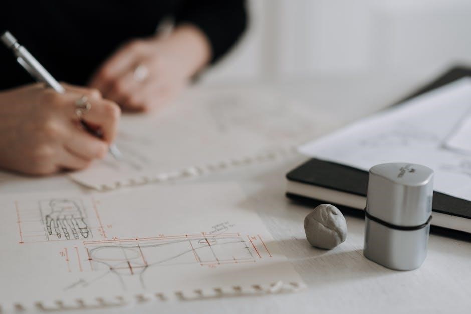
Engineering drawing exercises involve creating detailed component drawings and redesigning parts using metric or decimal dimensions, enhancing drafting skills and practical application of technical drawing concepts.
6.1. Detail Drawings for Components: Examples and Exercises
Detail drawings focus on precise representations of individual components, showcasing dimensions, tolerances, and material specifications. These exercises help develop skills in creating accurate technical illustrations. Examples include drafting machine parts like gears or brackets, ensuring adherence to engineering standards. Students often practice converting imperial to metric dimensions or vice versa. Redesigning components with updated measurements enhances understanding of manufacturing requirements. Exercises also involve interpreting CAD-generated detail drawings, emphasizing the importance of clarity and precision. By mastering these tasks, learners improve their ability to communicate design intent effectively, bridging the gap between conceptualization and production. These exercises are fundamental for fostering proficiency in technical drawing and engineering graphics.
6.2. Redesigning Parts with Metric or Decimal Dimensions
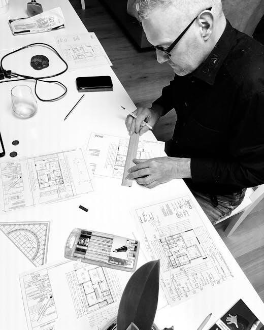
Redesigning parts involves adapting existing designs to meet specific dimensional requirements, such as converting between metric and decimal systems. This process enhances understanding of global engineering standards. Students learn to update component dimensions while maintaining functionality and manufacturability. Exercises often include recalculating tolerances and ensuring compliance with international norms. Redesign tasks also focus on optimizing part geometry for production, emphasizing the practical application of technical drawing skills. By engaging in these activities, learners develop proficiency in handling diverse measurement systems and preparing designs for real-world applications. This skill is crucial for collaborating in global engineering projects and ensuring design compatibility across different regions and industries.
Tools and Software for Technical Drawing
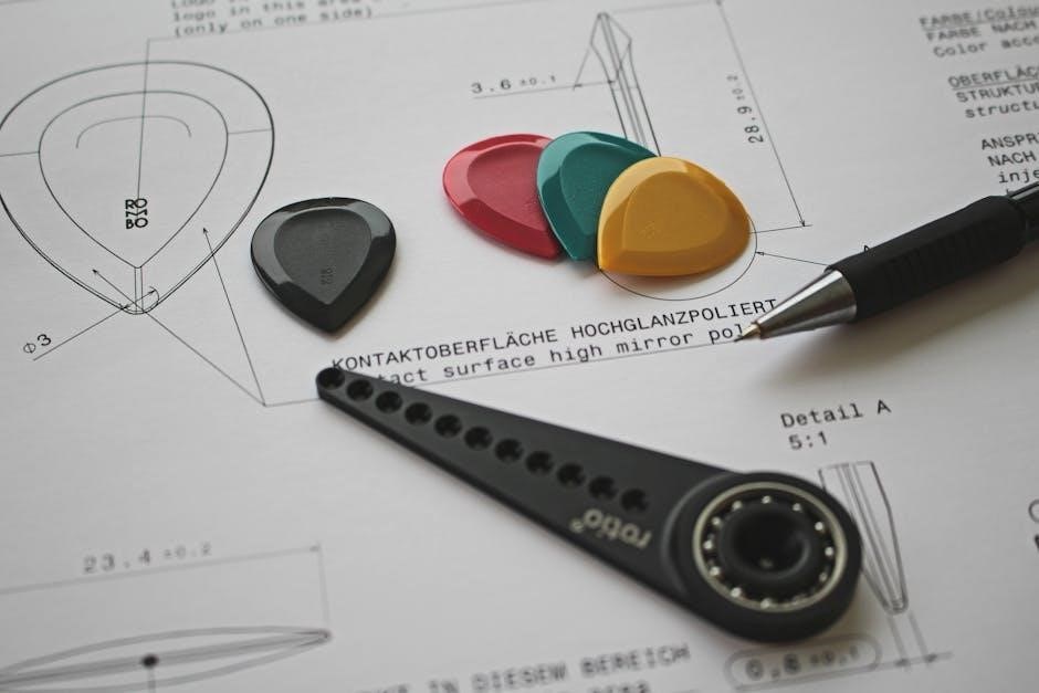
Popular CAD tools like CATIA and KOMPAS-3D enable precise 3D modeling and 2D documentation, streamlining the technical drawing process with advanced features and functionality.
7.1. Overview of Popular CAD Tools for Engineering Graphics
Popular CAD tools like CATIA, SolidWorks, and AutoCAD dominate engineering graphics, offering advanced features for 3D modeling and 2D documentation. These tools provide parametric modeling, libraries of standard components, and rendering capabilities. CATIA excels in complex surface modeling, while SolidWorks is known for user-friendly assembly design. AutoCAD remains a staple for 2D drafting and customization. Tools like NX and Creo also offer comprehensive solutions for engineering design. These software solutions enable precise technical drawings, fostering innovation and efficiency in the design process. They are widely used in education and industry, ensuring compatibility with modern engineering workflows and documentation standards.
7.2. Best Practices for Using Graphic Editors like KOMPAS 3D

When using graphic editors like KOMPAS 3D, start with precise 2D sketches, ensuring geometric constraints are applied for accuracy. Organize your project by creating separate layers for different components. Utilize the library of standard elements to streamline the design process. Regularly save and backup your work to avoid data loss. Iterate on your design by analyzing and refining 3D models. Leverage the software’s rendering tools to create photorealistic visuals for presentations. Finally, practice reverse engineering exercises to enhance your understanding of complex geometries. Mastery of these practices ensures efficient and high-quality technical drawings, aligning with industry standards and expectations.
